No matter which option you choose, Signalight will recommend a lighting scheme, a power supply scheme, and a configuration for the controller or command.
You can find here solutions for different types of heliports, different types of installations, models of heliport designs, and different kinds of lights.
We design custom Heliport Lighting systems or follow the requirements and designs of our customers. Depending on the location of the heliport, there are three systems we offer:
- Surface level heliports or ground heliports
- Elevated heliports
- Offshore heliports or helidecks
Ground heliports
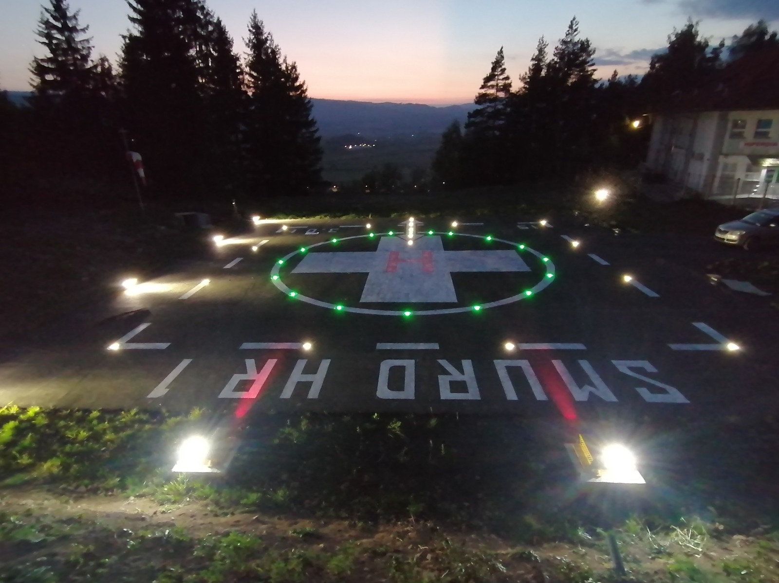
The ground heliports or surface-level heliports are located on the ground and usually have a large surrounding area. Many times, in one ground heliport, there are more helipads, taxiways, and helicopter parking lots or stands.
On the heliports there are more lights, with different purposes, all of them to assure a safe and precise landing or takeoff.
Examples of heliports on the ground:
Simulation:
Elevated heliports
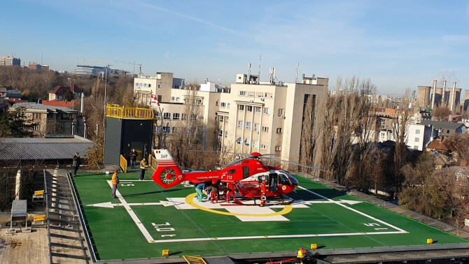
Elevated heliports are usually located on top of the buildings on platforms made of aluminum or concrete. In this case, the space is limited, and also the installation of bases and cables.
Example of elevated heliport:
Simulation:
Offshore helidecks
These are helidecks on oil platforms. Here the lighting system is made with lighting panels to create the letter H and the yellow circle around it.
Example of offshore helidecks:
Simulation:
Download presentation of Heliport Lighting Systems:
INSET heliport lights
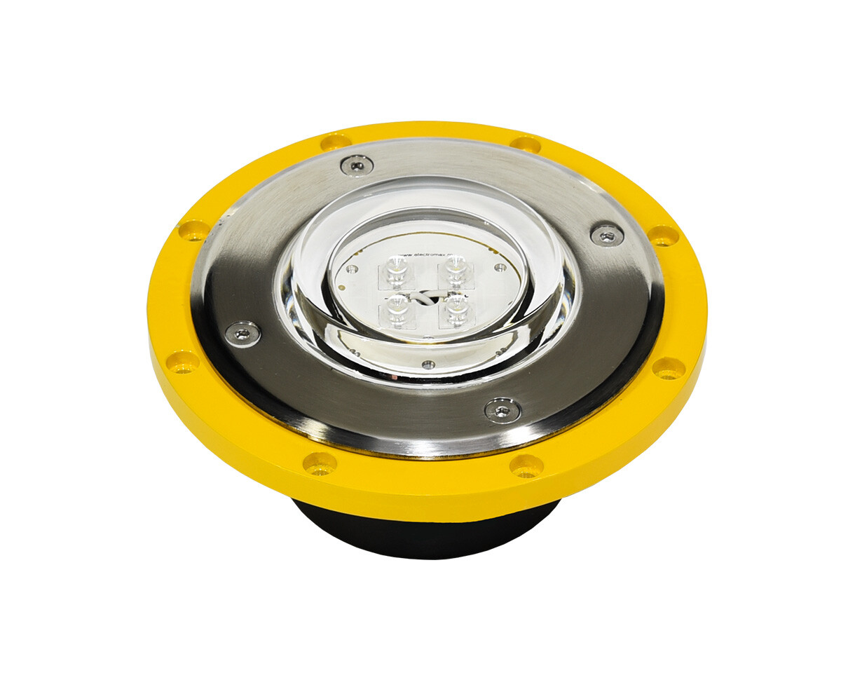
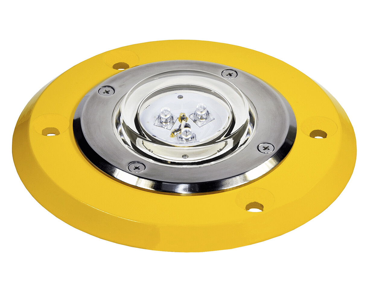
Heliport inset lights are LED underground lights mounted on shallow bases or base canes in helipad platforms for signaling the FATO, TLOF, AIMING, ALIGNMENT, or TAXI. These lights are installed in specially designed underground bases.
We designed a smaller base easier and cheaper to install in the helipad platform because it needs less drilling and less resin to be fixed in the concert. The deep is also lower than standard shallow bases, just 130 mm or even 100 mm. This is very useful when the platform is not that thick. This type of installation is usually used on ground heliports.
What type of heliport inset lights Signalight offers?
ELEVATED heliport lights
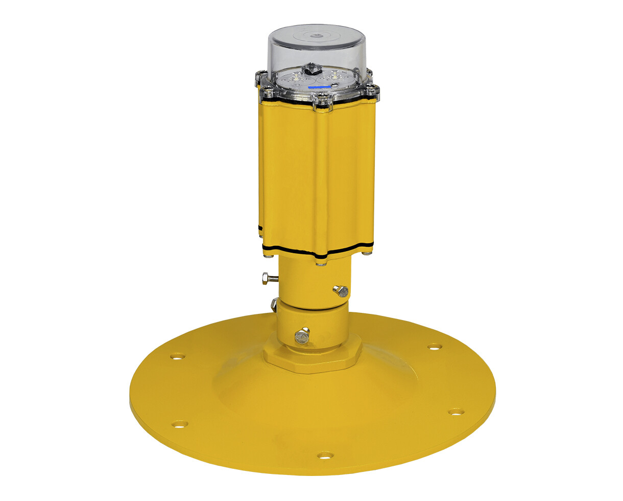
The heliport elevated lights are mounted on base plates with frangible coupling. On a ground or elevated heliport, the lights on the perimeter can be elevated. These lights can be WHITE or GREEN, depending on if the TLOF is combined or not with the FATO area.
TAXIWAY lights can be also elevated, the APPROACH lamps, and sometimes AIMING lights. An elevated light is easier to install because there is no need for a shallow base installed into the platform. The electrical connection is made under the base plate into a small space created to fit the junction box.
What type of heliport elevated lights Signalight offers?
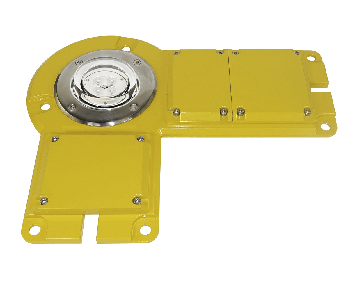
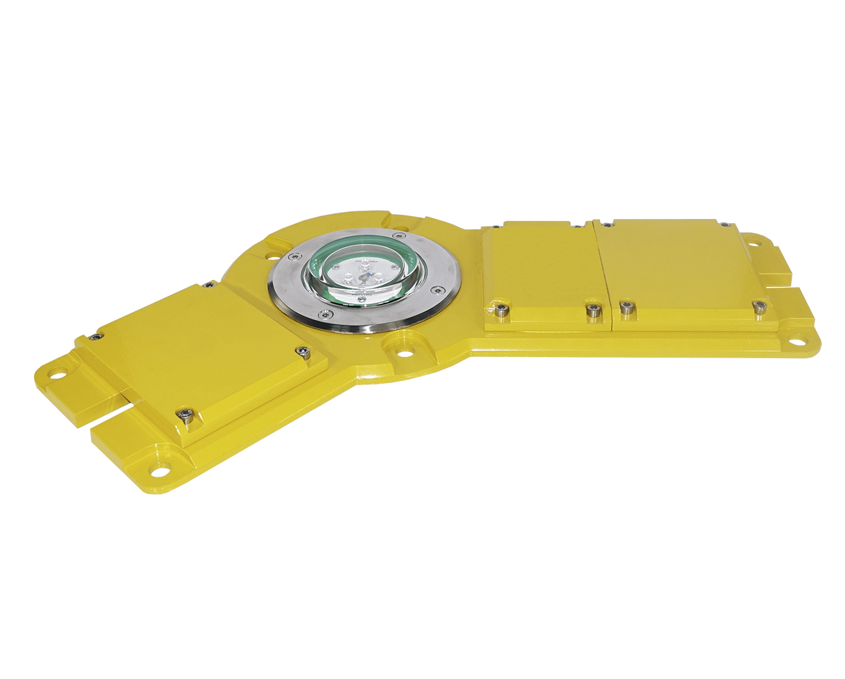
FLAT heliport lights
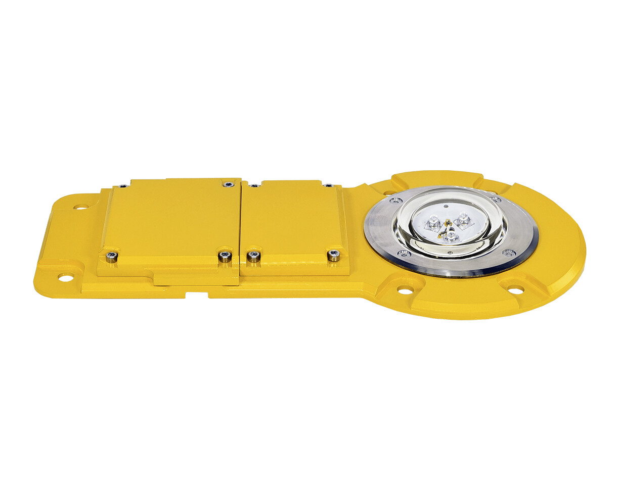
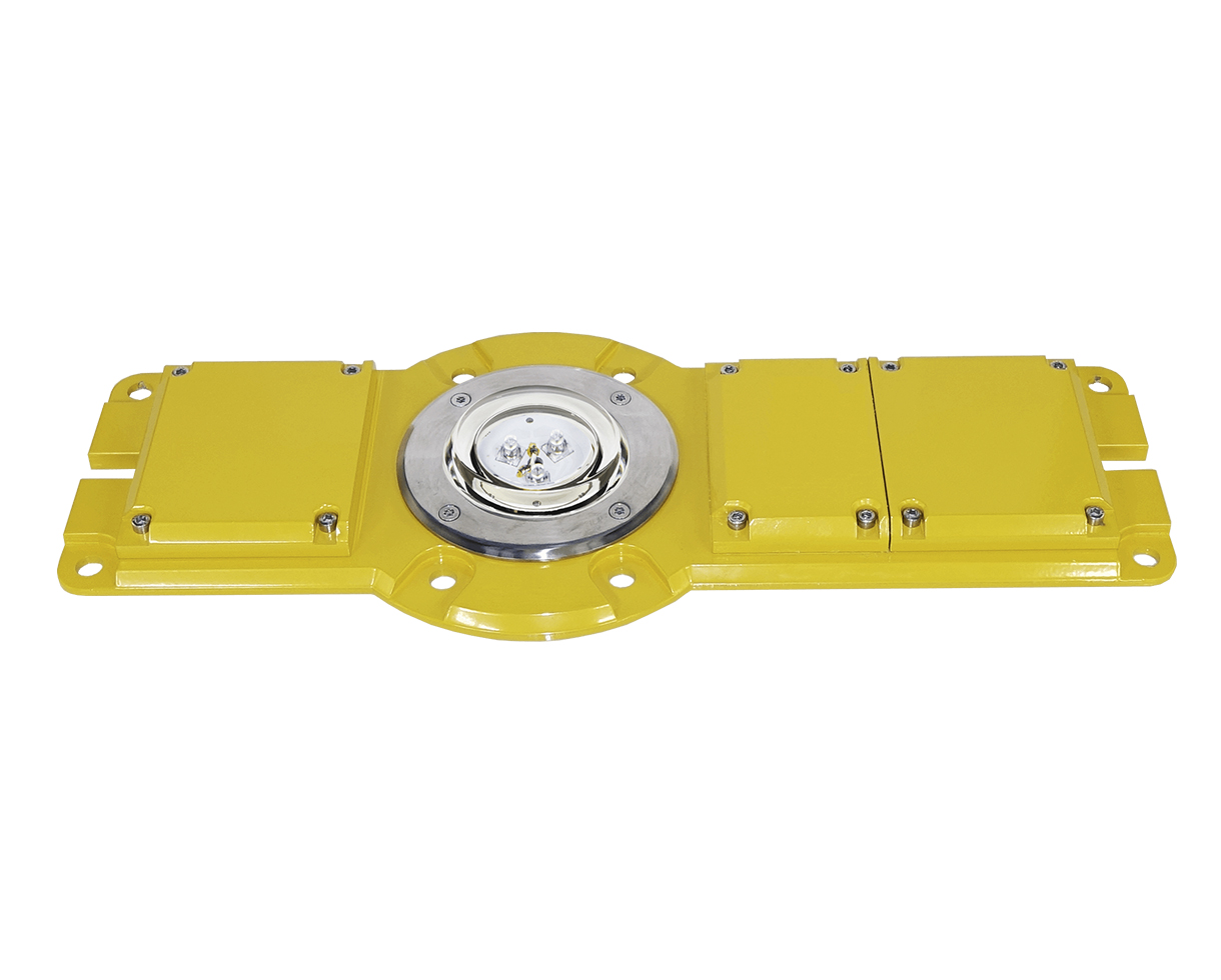
Heliport flat lights are designed for mounting directly on the surface of the helipad without a shallow base or trances for cables.
We propose two options, flat lights type F and flat lights type FD (with integrated junction boxes).
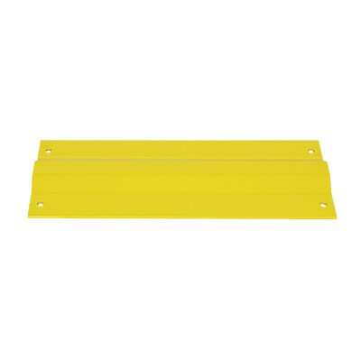
Aluminum profile used for cable protection in heliport lighting systems using flat lights.
The first type of light is used on elevated heliports where there is space under the platform to make the electrical connections. So you just have to drill a hole for the cable to cross through the platform. Under the platform, all connection boxes and cables can be later installed.
The second option is with flat lights with integrated junction boxes. All the cables are protected with aluminum profiles. This system is used on existing platforms. The installation is fast and cheap to be done.
Lighting heliport PANELS
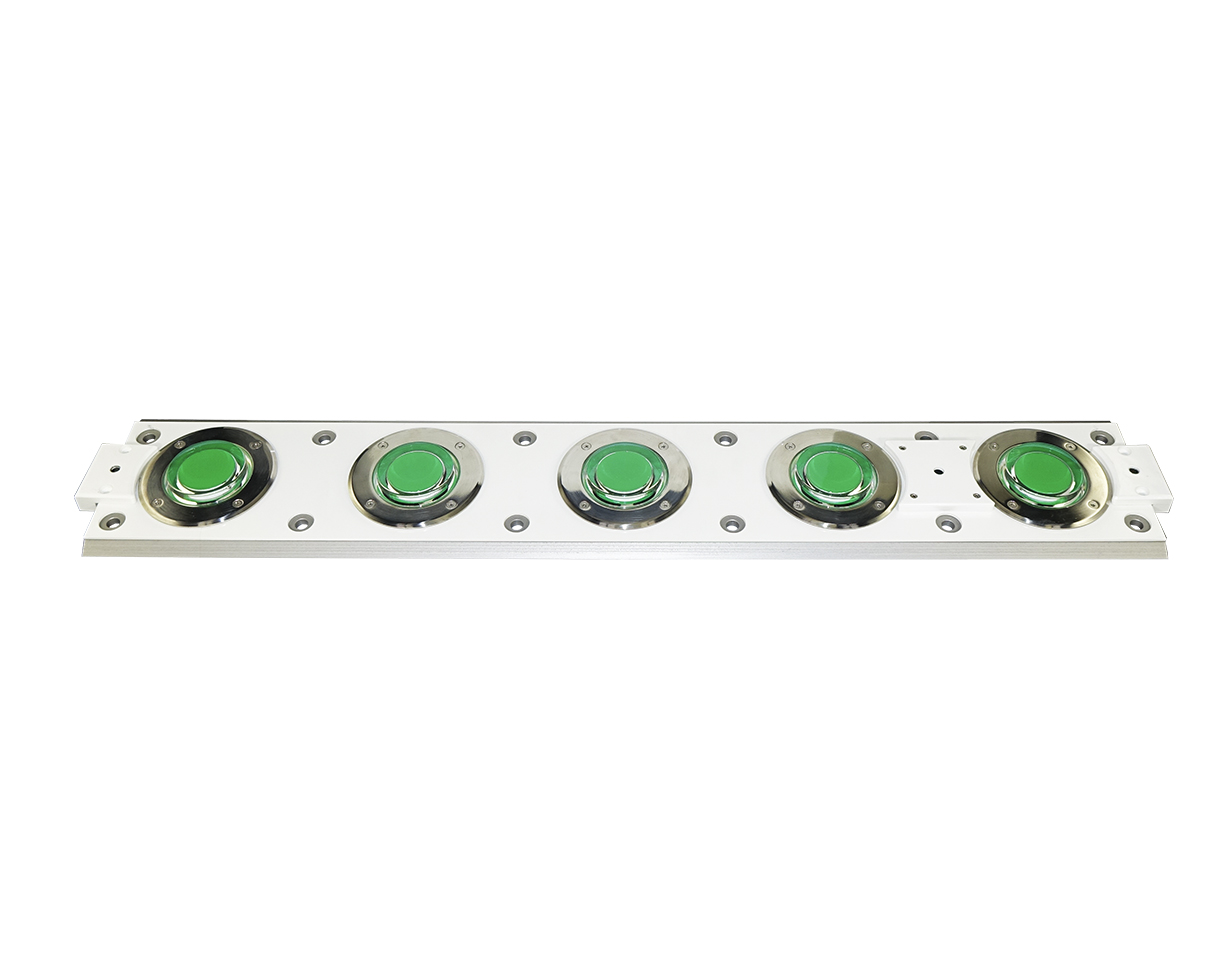
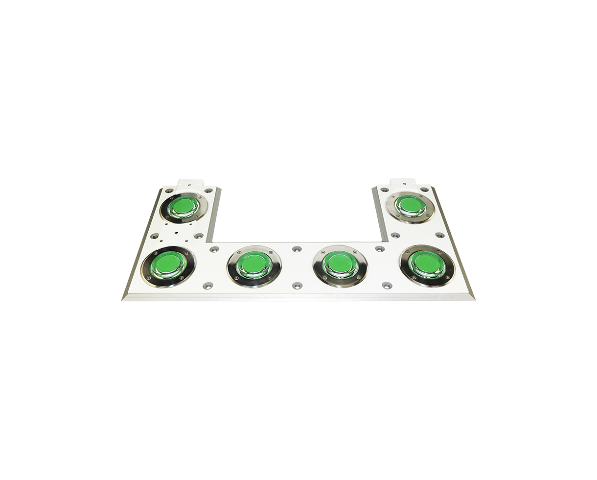
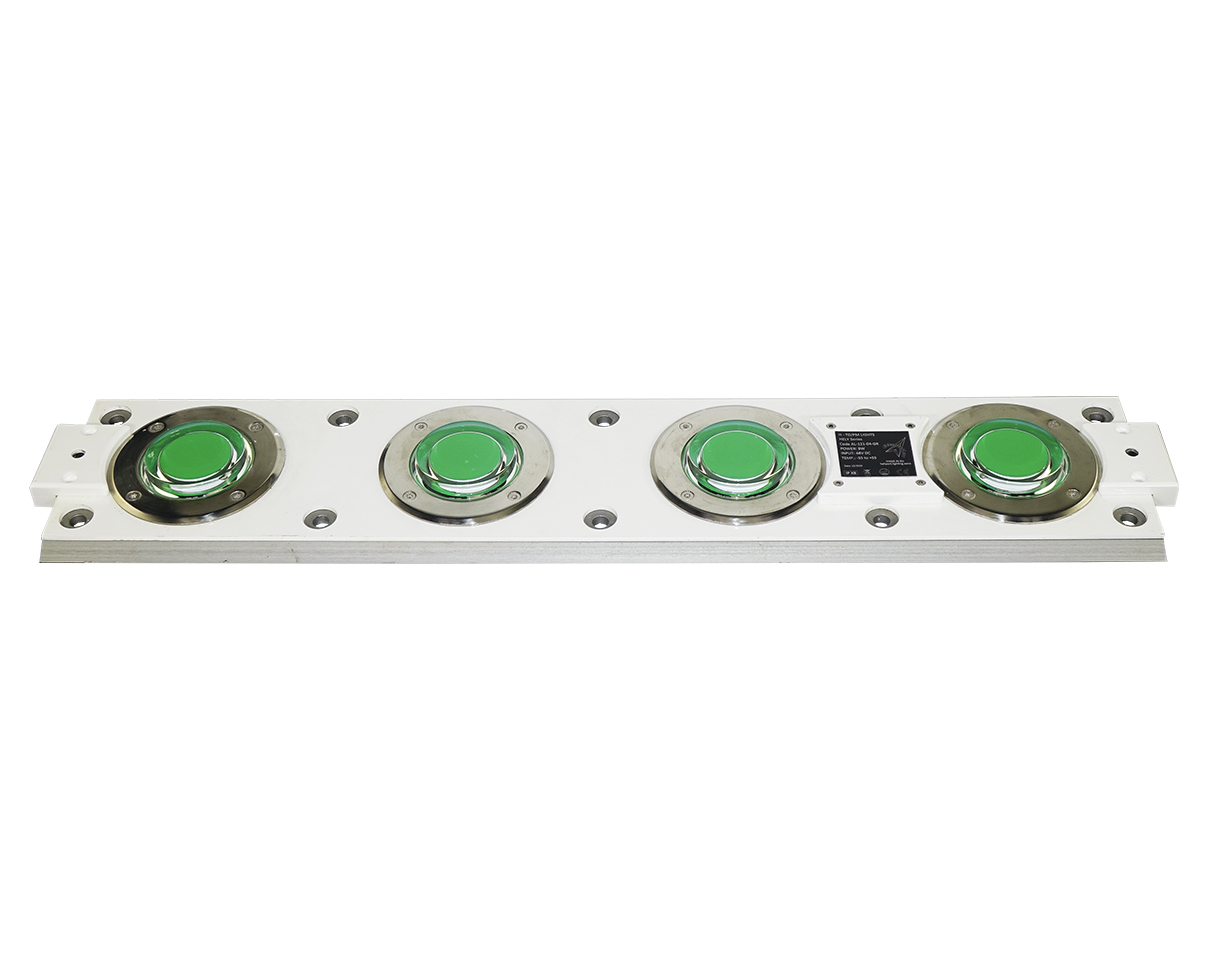
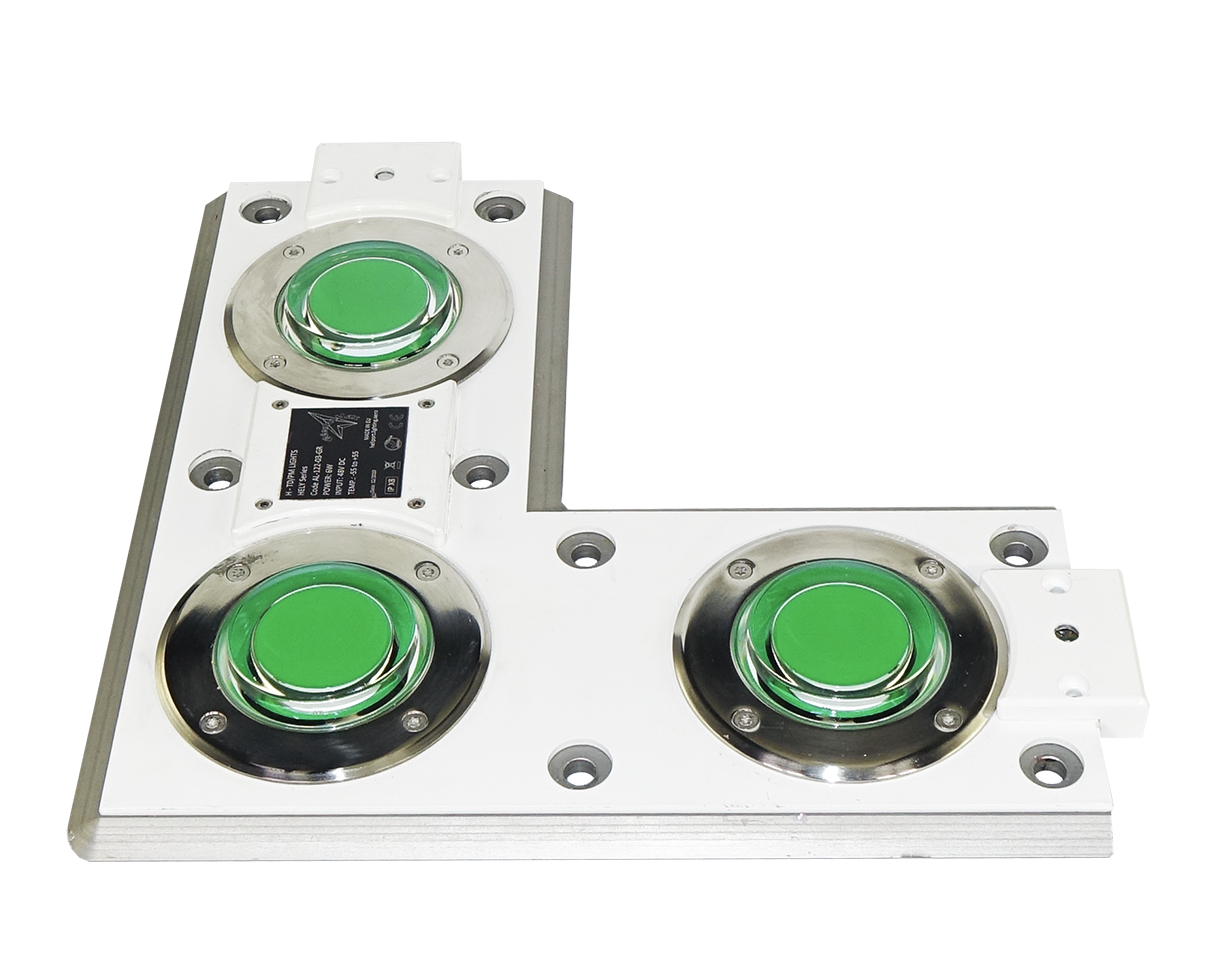
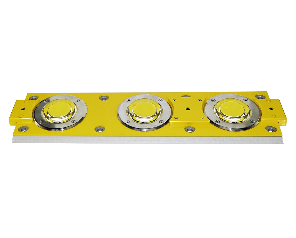
The lighting panels or TD/PM Circle-H panels are used on offshore helideck system for helicopter landing areas. With these panels we create the letter H in the middle of the helideck and the circle of yellow lights to indicate the TLOF area.
On oil rigs, the platform is made of metal and usually, there is no space or possibility to insert shallow bases. In this case, the panels must be installed directly on the platform. We propose fixing with welded bolts. The panels are made in different shapes. To create the H letter in the middle of the helideck there are U shape, L shape and I shape panels. For the circle, there are just I shape panels.
Download presentation of Heliport Lighting System:
The heliport lighting systems can be simple or more complex, depending on the location and on the environment.
Ground level heliport lighting systems
V1: The simplest heliport model. From now on, this model will get more and more complex as we progress.
- Heliport TLOF elevated light
- Wind direction indicator
- Heliport beacon (optional)
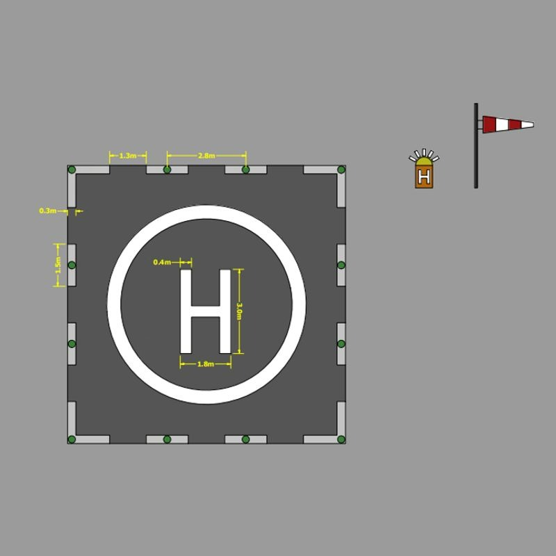
Heliport lighting system with perimeter lights
Example: https://www.signalight.com/projects/maidstone-hospital-heliport/
V2: Added:
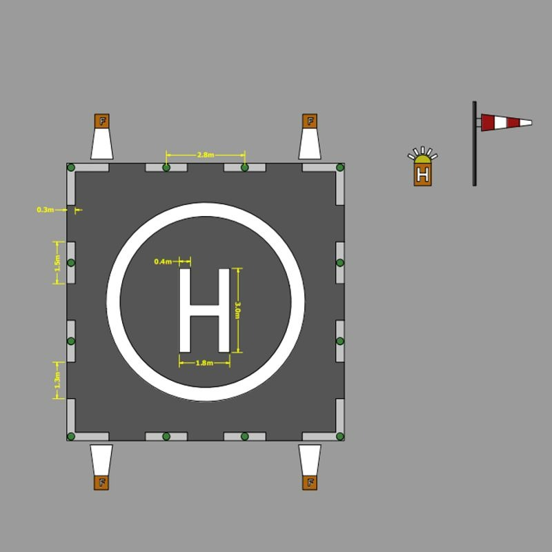
Heliport lighting system with perimeter lights and floodlights
Example: https://www.signalight.com/projects/heliport-on-wood-platform/
V3: Added:
- Heliport FATO Lighting System
- Taxiway lights (optional)
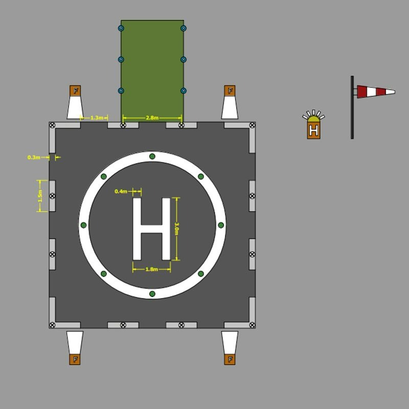
Heliport lighting system with TLOF, FATO, floodlights and TAXI
V4: Added:
- Flight Path Alignment Guidance Lights
- APAPI – indicates the approach angle; It can be replaced by HAPI or GPI.
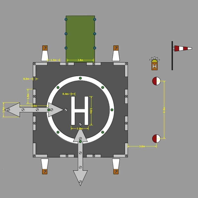
Heliport lighting system with TLOF, FATO, floodlights, allignment, APAPI and TAXI
Ex: https://www.signalight.com/projects/heliport-hospital-miercurea-ciuc/
V5: Added:
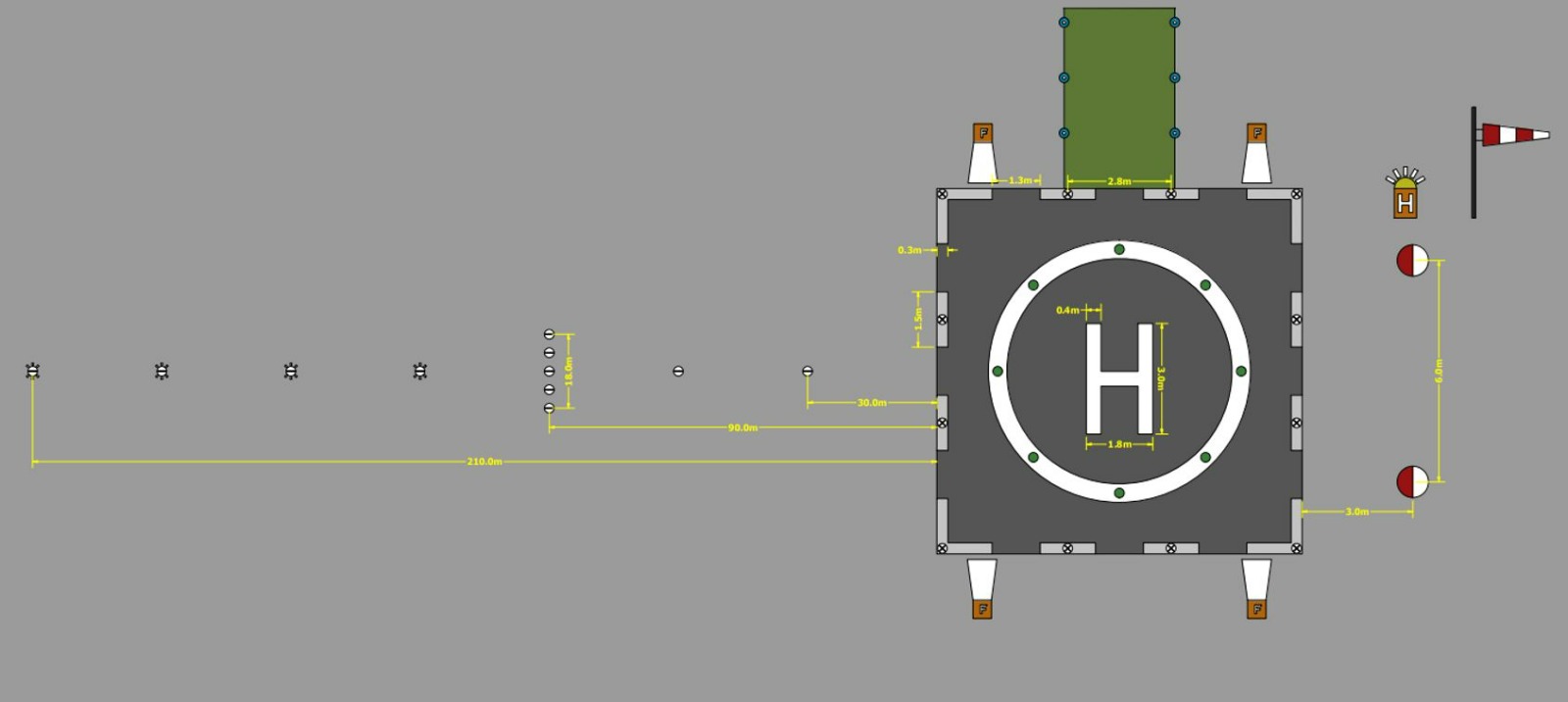
Heliport lighting system with TLOF, FATO, floodlights, allignment, approach, APAPI and TAXI
Elevated heliport lighting systems
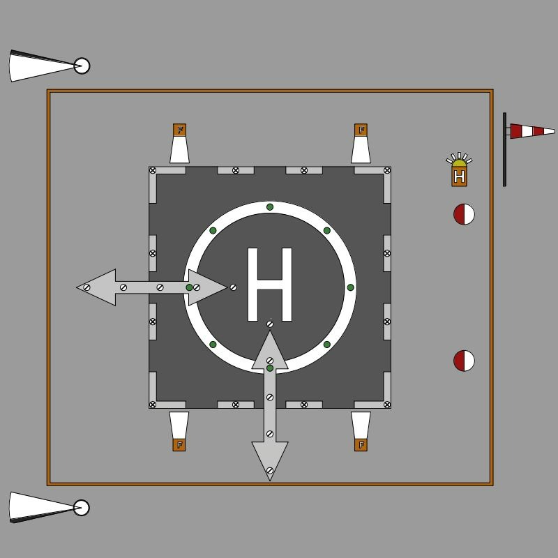
Elevated Heliport Lighting System
On the elevated heliports because of the space limitation, as approach system, we used the Visual Alignment Guidance System
Offshore helideck lighting systems
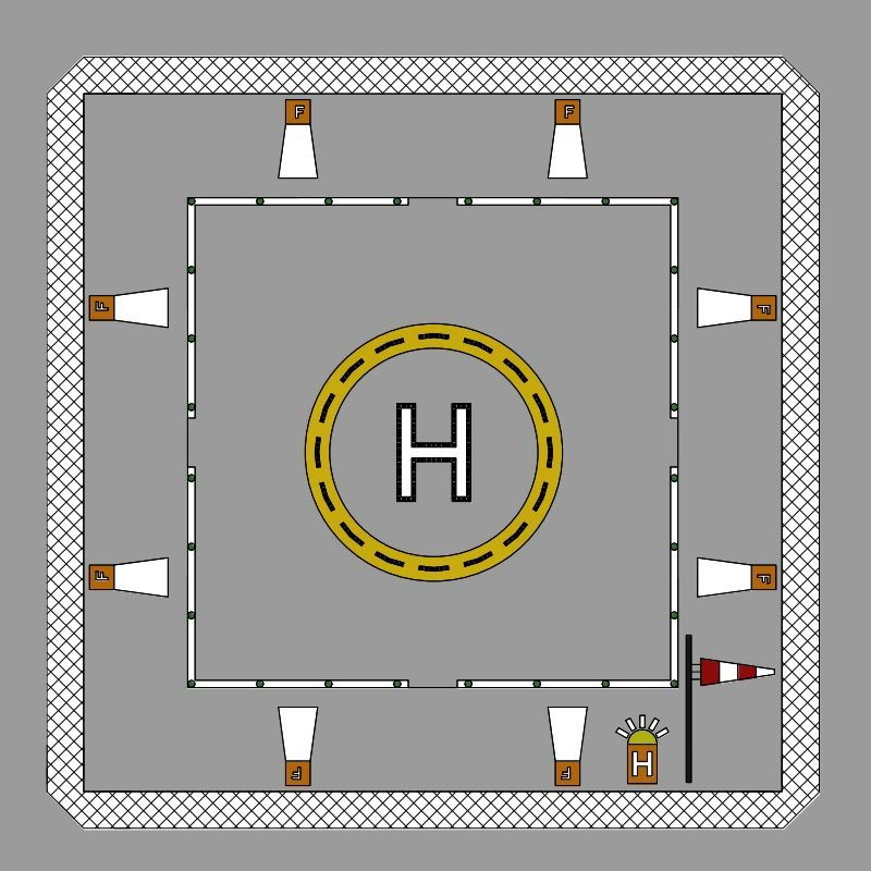
Offshore helideck lighting system
On the offshore platforms, the letter H is made of white lighting panels with green LEDs. The circle is made with yellow panes and yellow LEDs
The system is completed with green perimeter lights, a floodlight system, a wind direction indicator and a heliport beacon.
Download presentation of Heliport Lighting System:
The lights on the heliports have different purposes:
- Guidance
- Horizontal
- Vertical
- Marking lights
Guidance lights
These lights are for directing the pilots on the correct approach path. One of the first light a pilot should see is the heliport beacon.
Heliport beacon
A heliport beacon has a very strong beam, omnidirectional in white color signaling in a sequence of flashings the letter H in MORSE code.
The purpose is for the pilot to identify the location of the heliport from a long distance. It is used specially when the heliport is surrounded by lights usually in a city so the pilots can be disturbed and not see the position of the heliport so easily. After this the pilot should be guided in both horizontal and vertical plane. For the horizontal guidance on the ground heliports can be used the approach lighting system.
Simulation:
Heliport Approach lighting system
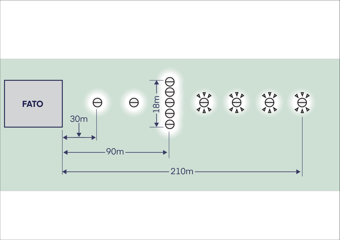
The approach lighting system is used to indicate the preferred landing direction.
For this system, elevated approach lights are used to create a row of three lights and a crossbar. Optional, where the final approach has to be more visible, additional sequence flashing lights can be used.
The schematic of the approach system is in the below picture.
APAPI – Abbreviated precision approach path indicator
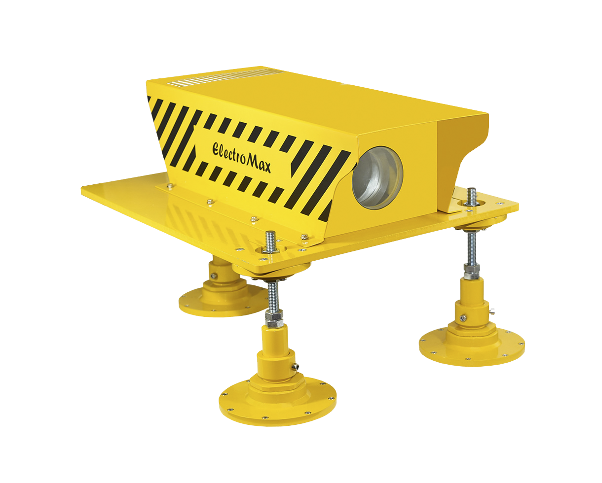
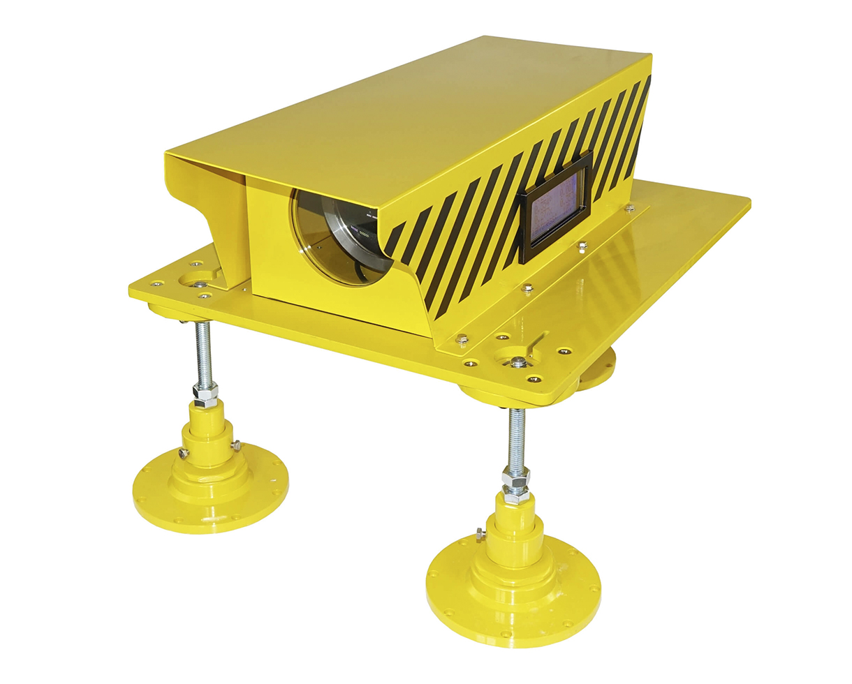
The abbreviated precision approach path indicator is made with two APAPI units.
Each projector has a beam divided in two where on the top we have white color and, on the bottom, we have red color. The two projectors are installed on different angles in vertical plane so the pilot will see three different combinations of colors to maintain the correct approach slope to the FATO:
- White – white – in this position the pilot is too high
- White – red – the pilot is on the correct path
- Red – red the pilot is too low
Simulation:
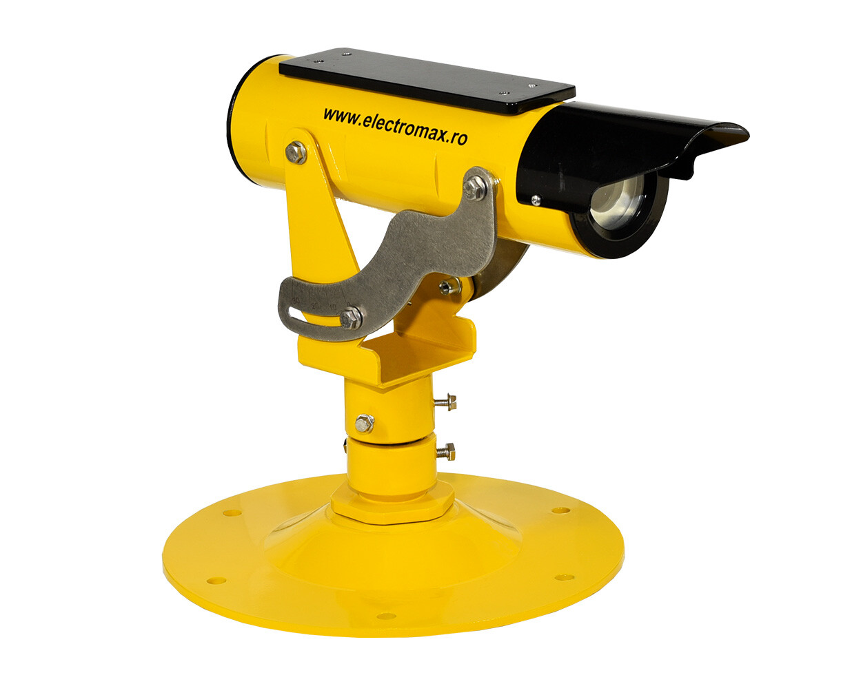
HAPI – Heliport approach path indicator
In a heliport approach path indicator (HAPI) system we have only one unit where the beam is divided in four:
- Flashing GREEN on the top
- Steady GREEN
- Steady RED
- Flashing RED on the bottom
The pilot is on the correct path when he is in the steady GREEN beam.
If the pilot sees the steady RED, it means it is slightly bellow
If the pilot sees flashing GREEN, it is too high and for the flashing RED it is too low.
Simulation:
GPI – glide path indicator
For the glide path indicator is needed just one unit.
The unit has three beams:
- YELLOW on the top
- GREEN in the middle
- RED on the bottom
The pilot is on the correct path when he is in the GREEN beam.
If the pilot sees the RED, it means it is too low.
If the pilot sees GREEN color, it is too high.
Simulation:
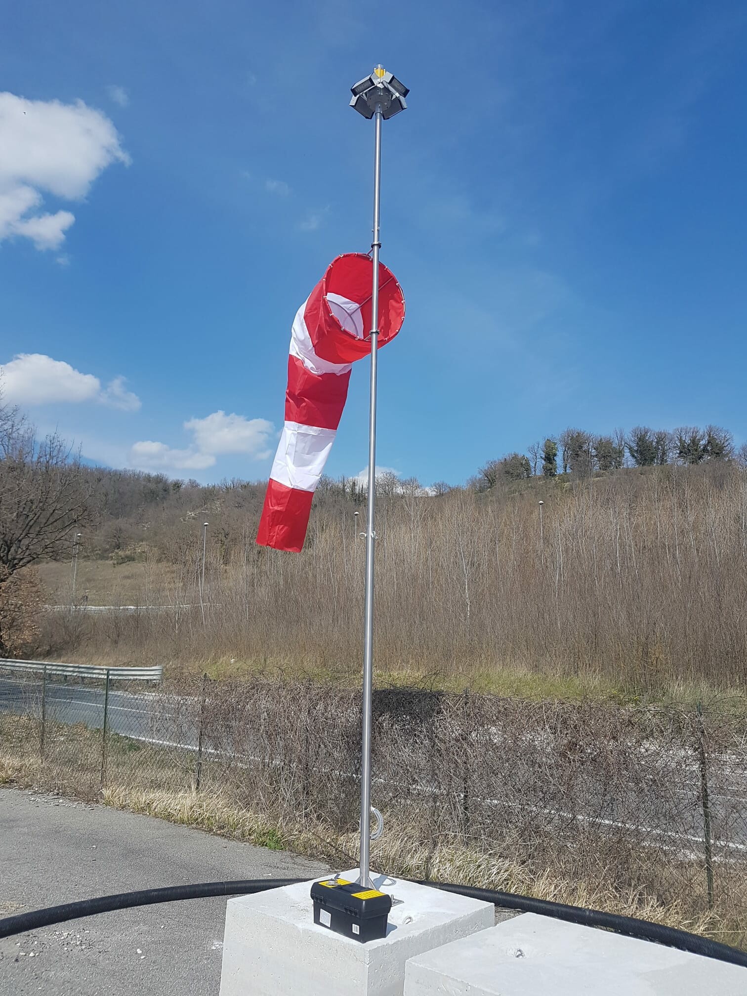
Heliport Wind direction indicator
When the pilot approaches the heliport, the 1st thing they shall see is the direction of the wind and its intensity. The wind cone gives a clear indication of the direction of the wind and a general indication of the wind speed. It shall be located so as to indicate the wind conditions over the FATO and TLOF and in such a way as to be free from the effects of airflow disturbances caused by nearby objects. It shall be visible from a helicopter in flight, in a hover or on the movement area. A heliport shall be equipped with at least one wind direction indicator. When the pilot approaches the heliport, the 1st thing they shall see is the direction of the wind and its intensity.
Heliport Marking lights
Heliport FATO Lighting System
The purpose of this system is to give the pilot an indication regarding the shape and the extent of the FATO. The lights should be on the edge of the FATO evenly spaced. If the FATO is a square then the lights can be 50 m apart, minimum of 4 lights on each side of the square including lights in the corner. If the FATO is a circle, then minimum 10 lights should be used and the distance between the lights should be maximum 5 m. The FATO lights can be INSET heliport FATO or ELEVATED FATO, not exceeding 250 mm. A complete system can be seen in our project in the Hospital heliport.
Heliport TLOF perimeter lights
Shall be uniformly spaced at intervals of not more than 5 m for surface-level heliports. There shall be a minimum number of four lights on each side including a light at each corner. For a circular TLOF where lights cannot be located on straight lines in a pattern, they shall be evenly spaced around the perimeter of the TLOF at the appropriate interval, except that over a sector of 45 degrees the lights shall be spaced at half spacing. There shall be a minimum of fourteen lights.
Heliport Flight Path Alignment Guidance Lights
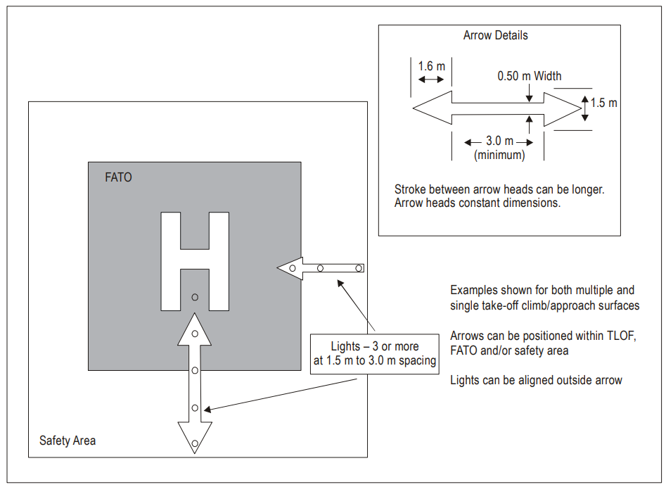
These lights are indicating the Approach and departure directions. The best is to use 5 lights in a row of a minimum of 6 m, with spaces between the lights of a minimum of 1.5 m but no more than 3 m. The Flight Path Alignment Guidance Lights can be combined with the guidance lighting, like in the picture below.
Heliport Aiming lights
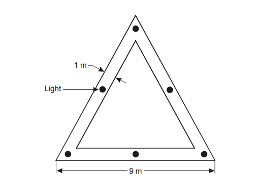
The objective of aiming point lights is to provide a visual cue indicating to the pilot by night the preferred approach / departure direction, the point to which the helicopter approaches to a hover before positioning to a TLOF where a touchdown can be made, and that the surface of the FATO is not intended for touchdown.
Aiming point lights shall form a pattern of at least six omnidirectional white lights as shown in the figure below. The lights shall be inset when a light extending above the surface could endanger helicopter operations.
Aiming Point Light System
Heliport Floodlights
The floodlight system is made with led projectors of 20W or 60W installed on the edge of the heliport to create a uniform illumination on the TLOF area. The average illuminance of the floodlight should be at least 10 lux, with a uniformity ratio (average to minimum) of no more than 8:1 measured on the surface of the TLOF.
Heliport Taxiway lights
ELEVATED Taxiway lights and INSET taxiway lights are used to provide continuous guidance between the helipad and the helicopter stands.
